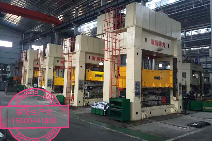
Frame hydraulic press
The frame hydraulic press has good structural rigidity, high precision, and strong anti-eccentric load capacity. The hydraulic control system uses a plug-in integrated system, which has reliable operation, long service life, and small hydraulic shock, which reduces the connection pipelines and leak points. Imported PLC The controlled electrical system has a compact structure, is sensitive and reliable, and is easy to use and maintain. It has three operation modes: adjustment, manual, semi-automatic, fixed stroke and fixed pressure. The bottom beam is equipped with a hydraulic pad. Through the operation panel selection, the hydraulic pad can realize three working cycles with ejection, no ejection and hydraulic pad blanking.
Application: Frame hydraulic presses are suitable for various stamping processes such as deep drawing, bending, forming, blanking, flanging, etc., especially for automotive parts, household appliances, kitchen appliances, tractors, motorcycles, aerospace, aviation and other fields.

Optional accessories: mobile worktable, punching buffer device, light curtain safety protection device, oil cooling device, displacement sensing device, touch industrial display screen, punching device (hydraulic or mechanical), quick clamping Mechanism, mold protection device, imported PLC and guide rail lubrication device.
No. | Parameter Name | Unit | YTL27 series single-acting sheet metal hydraulic press (frame hydraulic press) | ||||||||||
100 | 200 | 315 | 400 | 500 | 630 | 800 | 1000 | 1250 | 1500 | ||||
1 | Nomal force | KN | 1000 | 2000 | 3150 | 4000 | 5000 | 6300 | 8000 | 10000 | 12500 | 15000 | |
2 | Return force | KN | 100 | 450 | 600 | 650 | 900 | 1200 | 1200 | 1800 | 2500 | 3200 | |
3 | Max opening height | mm | 900 | 1100 | 1250 | 1350 | 1500 | 1500 | 1500 | 1500 | 1800 | 1800 | |
4 | Liquid cushion force | mm | 200 | 630 | 1600 | 2000 | 2000 | 2000 | 3000 | 3000 | 3500 | 4000 | |
5 | Hydraulic pad stroke | mm | 200 | 250 | 300 | 350 | 350 | 350 | 350 | 350 | 400 | 400 | |
6 | Slide stroke | mm | 600 | 700 | 800 | 800 | 900 | 900 | 900 | 900 | 900 | 900 | |
7 | Slider forming speed | No load down | mm/s | 120 | 100 | 100 | 100 | 100 | 80 | 80 | 80 | 80 | 80 |
Work | mm/s | 14 | 15 | 10 | 9 | 14 | 10 | 16 | 12 | 9 | 14 | ||
Return | mm/s | 120 | 70 | 60 | 50 | 70 | 55 | 90 | 65 | 45 | 70 | ||
8 | Hydraulic pad formation speed | Push-out | mm/s | 50 | 40 | 20 | 15 | 30 | 30 | 30 | 30 | 30 | 30 |
Return | mm/s | 100 | 80 | 40 | 30 | 60 | 60 | 60 | 60 | 60 | 60 | ||
9 | Effective workbench size | Left and right | mm | 850 | 1000 | 1200 | 1200 | 1500 | 3000 | 3000 | 3000 | 3000 | 3000 |
Front and back | mm | 600 | 800 | 1200 | 1200 | 1200 | 1600 | 1800 | 2000 | 2000 | 2000 | ||
10 | Hydraulic pad size | Left and right | mm | 650 | 600 | 800 | 800 | 1000 | 2200 | 2200 | 2200 | 2200 | 2200 |
Front and back | mm | 400 | 500 | 800 | 800 | 800 | 1200 | 1250 | 1500 | 1500 | 1500 | ||
11 | Mobile workbench load | T |
|
|
|
| 15 | 15 | 15 | 15 | 20 | 20 | |
12 | Motor power | KW | 7.5 | 15 | 22 | 22 | 44 | 50 | 60 | 70 | 80 | 160 | |

